
ANSI/ISA 5.1-2024 defines graphical symbols for P&IDs‚ depicting sensors‚ valves‚ and automation components; wermac.org offers valuable resources.
What are Piping and Instrumentation Diagrams (P&IDs)?
Piping and Instrumentation Diagrams (P&IDs) are detailed schematics illustrating the piping‚ equipment‚ instrumentation‚ and control systems within a process plant. They serve as a blueprint for the entire facility‚ showcasing the interconnectedness of various components. Unlike a Process Flow Diagram (PFD) which focuses on the major process steps‚ P&IDs delve into granular detail‚ including pipe specifications‚ valve types‚ and instrument tagging.
These diagrams are crucial for engineering design‚ operation‚ maintenance‚ and safety reviews. They visually represent the physical piping layout alongside the control loops and instrumentation used to monitor and control the process. Understanding P&ID symbols is paramount for anyone involved in process engineering‚ ensuring accurate interpretation and effective communication. Resources like wermac.org provide comprehensive guides and symbol libraries.
Importance of Standardized Symbols
Standardized symbols within P&IDs are absolutely critical for clear communication and avoiding misinterpretations across diverse engineering teams and disciplines. Without a common language of symbols‚ understanding process schematics becomes incredibly difficult‚ potentially leading to costly errors during construction‚ operation‚ or maintenance.
The ANSI/ISA 5.1-2024 standard ensures consistency in symbol representation‚ facilitating seamless collaboration between engineers‚ operators‚ and technicians. Utilizing these standardized symbols minimizes ambiguity and promotes safety. Resources like wermac.org and online libraries offer downloadable P&ID symbol PDFs and DWG files‚ reinforcing adherence to these vital standards. Consistent application of these symbols is fundamental to effective process plant management.
ANSI/ISA 5.1-2024 Standard
The ANSI/ISA 5.1-2024 standard is the cornerstone for graphical symbol representation in Piping and Instrumentation Diagrams (P&IDs). It meticulously defines symbols for instrumentation – sensors‚ controllers‚ transmitters‚ and indicators – alongside conventions for tagging these components. This standard ensures uniformity‚ crucial for accurate interpretation across projects and organizations.
Access to resources detailing this standard‚ often available as P&ID symbol PDFs and DWG libraries (like those found on wermac.org)‚ is essential for engineers. The standard covers identification methods‚ promoting clarity and reducing potential errors. Adherence to ANSI/ISA 5.1-2024 is paramount for safe and efficient process plant design and operation‚ fostering a universally understood visual language.

Piping Symbols
Piping systems include pipes‚ fittings‚ and flanges; P&IDs utilize specific line types to represent different piping specifications and materials effectively.
Pipe Representation and Line Types
Piping and Instrumentation Diagrams (P&IDs) employ standardized line types to clearly represent various piping characteristics. These lines differentiate between process‚ utility‚ and vent/drain systems. A solid line typically indicates a process pipe carrying fluids‚ while dashed or dotted lines signify different services like steam or instrument air.
Line width often correlates to pipe size‚ providing a visual indication of diameter. Double lines can represent insulated pipes‚ and lines with specific markings denote special materials or tracing. Understanding these conventions is crucial for accurately interpreting a P&ID. The ANSI/ISA 5.1-2024 standard meticulously defines these representations‚ ensuring consistency across engineering disciplines and projects. Proper line type usage enhances clarity and minimizes misinterpretation during design‚ operation‚ and maintenance.
Different Pipe Sizes and Specifications
P&IDs don’t typically display exact pipe dimensions but visually indicate relative sizes through line thickness. Larger diameter pipes are represented by thicker lines‚ offering a quick visual assessment. However‚ accompanying documentation‚ like a piping bill of materials‚ provides precise specifications – including nominal pipe size (NPS)‚ schedule number (wall thickness)‚ and material grade (e.g.‚ carbon steel‚ stainless steel).
These specifications adhere to standards from organizations like ASME‚ ASTM‚ and API. Understanding these standards is vital for ensuring structural integrity and compatibility with process fluids. The ANSI/ISA 5.1-2024 standard focuses on graphical representation‚ while detailed sizing and material information are found in separate project documents. Accurate specification is critical for safe and reliable operation.
Pipe Fittings Symbols
P&ID symbols for pipe fittings are standardized to clearly represent components like elbows‚ tees‚ reducers‚ and couplings. These symbols‚ defined by ANSI/ISA 5.1-2024‚ are simplified graphical representations‚ not detailed drawings. Elbows are shown as curved lines indicating direction‚ while tees depict branching points. Reducers illustrate changes in pipe diameter‚ and couplings represent straight connections.
Wermac.org and online P&ID symbol libraries provide visual examples of these fittings. While the symbols themselves don’t specify size or material‚ these details are documented elsewhere. Correctly interpreting these symbols is crucial for understanding flow paths and system layout. Accurate representation of fittings ensures clarity and facilitates effective communication among engineers and designers.
Flange Symbols
Flange symbols on P&IDs‚ as detailed in ANSI/ISA 5.1-2024‚ represent connection points between pipe sections or components. They are depicted as circles bisecting the pipeline‚ indicating the flange’s location. Different flange types aren’t typically distinguished graphically on a basic P&ID; specifications like pressure rating and material are noted separately in accompanying documentation.
Resources like wermac.org showcase standard flange representations. These symbols are essential for understanding where equipment connects within a piping system. While simplified‚ they clearly indicate potential disassembly points for maintenance or inspection. Correctly interpreting flange symbols is vital for process engineers and designers‚ ensuring accurate system representation and facilitating effective communication.

Instrumentation Symbols
ANSI/ISA 5.1-2024 standardizes symbols for sensors‚ controllers‚ and transmitters on P&IDs‚ crucial for depicting process automation components effectively.
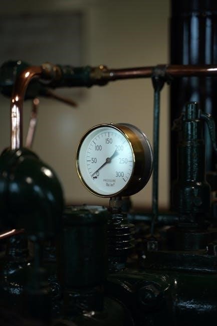
Sensor Symbols (Temperature‚ Pressure‚ Flow)
P&ID sensor symbols‚ governed by ANSI/ISA 5.1-2024‚ visually represent devices measuring process variables. Temperature sensors utilize a circle with a thermometer symbol inside‚ indicating temperature detection. Pressure sensors are depicted as squares with a diaphragm or capsule symbol‚ signifying pressure measurement. Flow sensors employ diamonds‚ often with an arrow indicating flow direction‚ to represent fluid or gas flow rate;
These symbols are fundamental for understanding process control loops. Different configurations denote field-mounted versus indicating sensors. Tagging conventions‚ also defined by the standard‚ uniquely identify each sensor within the P&ID. Understanding these symbols is vital for engineers interpreting and creating accurate process diagrams‚ ensuring clear communication and efficient plant operation. Resources like wermac.org provide detailed examples and explanations of these symbols.
Controller Symbols
Controller symbols on P&IDs‚ as standardized by ANSI/ISA 5.1-2024‚ represent devices that manipulate process variables based on sensor input. A typical controller symbol is a circle containing a controller symbol – often a diamond or a rectangle within. These symbols indicate the control function being performed‚ such as maintaining a specific temperature or pressure.
Different configurations denote various controller types‚ including single-loop and cascade control. Tagging conventions uniquely identify each controller‚ facilitating clear communication. Controllers receive signals from sensors and send output signals to control elements like valves. Understanding these symbols is crucial for interpreting process automation logic. Online P&ID symbol libraries and resources like wermac.org offer comprehensive details and examples for accurate diagram interpretation.
Transmitter Symbols
Transmitter symbols on P&IDs‚ governed by ANSI/ISA 5.1-2024‚ represent devices converting process measurements into standardized signals. These signals are then sent to controllers or monitoring systems. A common transmitter symbol features a square enclosing a symbol representing the measured variable – like a filled circle for temperature or a spring for pressure.
The square indicates the signal transmission function. Tagging conventions are vital for identifying each transmitter uniquely. Transmitters are essential for remote monitoring and control‚ providing real-time process data. Resources like wermac.org and online P&ID symbol libraries offer detailed examples and explanations. Accurate interpretation of transmitter symbols is key to understanding process automation and control loops within a plant.
Indicator Symbols
Indicator symbols on P&IDs‚ as defined by ANSI/ISA 5.1-2024‚ visually represent displays used to show process values to operators. These are typically local displays showing readings from instruments like transmitters or controllers. A common indicator symbol is a circle with a line through it‚ signifying a visual display.
Unlike controllers‚ indicators don’t typically perform control actions; they simply present information. Proper identification through tagging is crucial for clarity. Resources like wermac.org provide comprehensive symbol libraries. Understanding indicator symbols is vital for operators monitoring process conditions. Accurate P&ID interpretation relies on recognizing these symbols and their function within the overall control scheme‚ ensuring safe and efficient plant operation.
Valve Symbols
P&IDs utilize specific symbols – circles‚ diamonds‚ and others – to represent various valve types like globe‚ gate‚ ball‚ and check valves‚ per ANSI/ISA.
Globe Valve Symbols
Globe valve symbols on P&IDs‚ as defined by ANSI/ISA 5.1-2024‚ are crucial for accurately representing these throttling valves within a process flow diagram. Typically‚ a globe valve is depicted as a circle with a horizontal line bisecting it‚ indicating the valve’s closure member. Variations exist to denote specific functionalities‚ such as a ‘T’ shape within the circle signifying a three-way globe valve.
Understanding these symbols is vital for engineers interpreting P&IDs. The symbol clearly communicates the valve’s purpose – controlling flow through throttling – and its position within the piping system. Wermac.org and online DWG libraries provide detailed visual references for these symbols‚ ensuring consistent interpretation across projects. Correctly identifying globe valve symbols aids in troubleshooting‚ maintenance‚ and overall process understanding.
Gate Valve Symbols
Gate valve symbols‚ standardized by ANSI/ISA 5.1-2024‚ are essential for clear representation on Piping and Instrumentation Diagrams (P&IDs). These valves‚ primarily used for on/off service‚ are depicted as a circle with a horizontal line‚ often shorter than that used for globe valves‚ signifying a straight-through flow path when open. The symbol’s simplicity reflects the valve’s function – minimal obstruction to flow.
Accurate interpretation of these symbols is crucial for process engineers. P&ID symbols for gate valves distinguish them from throttling valves like globe valves. Resources like Wermac.org and downloadable DWG libraries offer detailed visual guides. Understanding gate valve symbols aids in quickly assessing flow isolation points within a system‚ supporting maintenance planning and safety assessments. Consistent symbol usage ensures clarity and avoids misinterpretation.
Ball Valve Symbols
Ball valve symbols‚ as defined within ANSI/ISA 5.1-2024 standards and commonly found in P&ID symbols PDF resources‚ represent quarter-turn valves utilizing a ball with a bore to control flow. The symbol typically features a circle with a semi-circular arc inside‚ indicating the ball’s position. This distinct visual cue differentiates it from other valve types on P&IDs.
These valves‚ known for quick operation and tight shut-off‚ are vital in many process applications. Wermac.org and online DWG libraries provide comprehensive visual references for accurate symbol interpretation. Correctly identifying ball valve symbols is crucial for understanding system functionality and troubleshooting. Consistent application of these standardized symbols ensures clarity and minimizes errors in process documentation and engineering designs.
Check Valve Symbols
Check valve symbols‚ detailed in ANSI/ISA 5.1-2024 and readily available in P&ID symbols PDF guides‚ illustrate unidirectional flow prevention. The standard symbol depicts a triangle pointing in the direction of permitted flow‚ often within a valve body outline. This clear visual representation signifies that the valve automatically opens to allow flow in one direction and closes to prevent backflow.
These valves are essential for protecting equipment and maintaining process integrity. Resources like Wermac.org offer detailed examples and explanations. Accurate interpretation of check valve symbols on P&IDs is critical for understanding system operation and ensuring safe‚ efficient fluid transport. Consistent use of standardized symbols‚ found in DWG libraries‚ promotes clarity and reduces potential misinterpretations during design and maintenance.
Control Valve Symbols
Control valve symbols‚ as defined by ANSI/ISA 5.1-2024 and detailed in numerous P&ID symbols PDF resources‚ represent valves modulating flow based on a signal. The symbol typically features a diamond shape connected to the valve body‚ indicating the actuator and control mechanism. Variations exist to denote different actuator types – pneumatic‚ electric‚ or hydraulic – each with specific graphical representations.
Understanding these symbols is crucial for interpreting P&IDs and grasping automated process control. Wermac.org provides comprehensive examples and explanations. Accurate depiction in DWG libraries ensures clarity during design and maintenance. Proper identification of control valves‚ through standardized symbols‚ is vital for troubleshooting and optimizing process performance‚ preventing errors and ensuring system reliability.

Component Symbols
P&ID symbols PDF resources detail components like pumps‚ tanks‚ heat exchangers‚ and mixers‚ essential for representing process equipment graphically.
Pump Symbols
Pump symbols on P&IDs‚ often found within Piping and Instrumentation Diagram symbols PDF guides‚ visually represent equipment used to transfer fluids. These symbols typically depict a stylized pump casing‚ often with arrows indicating the direction of flow. Different pump types – centrifugal‚ positive displacement‚ and others – may have slightly varied symbol representations‚ though standardized conventions exist within ANSI/ISA 5.1-2024.
The symbol’s orientation indicates flow direction‚ and accompanying tags identify the pump’s specific function and control parameters. Wermac.org and online P&ID symbol libraries provide detailed examples. Understanding these symbols is crucial for interpreting process flow and control strategies within a plant’s documentation‚ ensuring accurate system representation and maintenance procedures.
Tank Symbols
Tank symbols‚ readily available in Piping and Instrumentation Diagram symbols PDF resources‚ illustrate vessels used for storing liquids or gases. Typically‚ these symbols are represented as a rectangle or cylinder‚ often with a dome-shaped top. Variations exist to denote specific tank features‚ such as agitators‚ heating/cooling jackets‚ or internal components.
ANSI/ISA 5.1-2024 standardizes these representations for clarity. P&ID documentation utilizes these symbols alongside tagging conventions to identify tank contents‚ capacity‚ and associated instrumentation. Resources like wermac.org offer comprehensive libraries. Correct interpretation of tank symbols is vital for understanding process storage capacity‚ level control‚ and overall system functionality‚ aiding in efficient plant operation and safety.
Heat Exchanger Symbols
Heat exchanger symbols‚ found within Piping and Instrumentation Diagram symbols PDF guides‚ depict equipment transferring thermal energy between fluids. These are commonly represented as a rectangle divided into sections‚ symbolizing the hot and cold fluid paths. Variations illustrate different exchanger types – shell-and-tube‚ plate‚ or air-cooled – each with unique graphical representations.
ANSI/ISA 5.1-2024 standardizes these depictions for consistent P&ID interpretation. Wermac.org provides detailed examples. Proper understanding of these symbols is crucial for analyzing process heating or cooling stages‚ identifying flow paths‚ and assessing temperature control loops. Accurate representation ensures clear communication of thermal transfer processes within the plant‚ supporting efficient design and operation.
Mixer Symbols
Mixer symbols‚ detailed in Piping and Instrumentation Diagram symbols PDF resources‚ represent equipment used for blending fluids. Typically‚ a mixer is shown as a circle with an internal symbol indicating the mixing mechanism – an impeller‚ propeller‚ or static mixing elements. These symbols clearly illustrate the location of mixing within the process flow.
ANSI/ISA 5.1-2024 provides standardized representations for various mixer types. Wermac.org offers visual examples aiding in accurate P&ID interpretation. Understanding these symbols is vital for analyzing blending operations‚ identifying agitator drives‚ and assessing control loops related to mixing intensity. Correct depiction ensures clear communication of mixing processes‚ supporting efficient process design and operational troubleshooting.
P&ID Tagging and Identification
P&ID tagging conventions‚ found in symbols PDF guides‚ uniquely identify instruments‚ valves‚ and piping for clear process documentation and control.
Tagging Conventions for Instruments
Instrument tagging‚ detailed in P&ID symbols PDF resources‚ follows a standardized system for unambiguous identification. Typically‚ a three-letter designation indicates the measured variable – for example‚ ‘FT’ for Flow Transmitter‚ ‘PT’ for Pressure Transmitter‚ and ‘TT’ for Temperature Transmitter.
This is followed by a sequential number unique within the diagram. Further modifiers can denote specific aspects like reading or service. Understanding these conventions‚ readily available through resources like wermac.org‚ is crucial for interpreting P&IDs. Consistent tagging ensures clear communication between engineering disciplines‚ facilitating efficient operation‚ maintenance‚ and troubleshooting of process systems. Proper tagging‚ as outlined in ANSI/ISA 5.1-2024‚ minimizes confusion and errors.
Tagging Conventions for Valves
Valve tagging conventions‚ detailed within P&ID symbols PDF guides‚ utilize a standardized approach for clear identification. A typical tag begins with a two-letter prefix indicating valve function – ‘CV’ for Control Valve‚ ‘PV’ for Pressure Relief Valve‚ and ‘DV’ for Diaphragm Valve are common examples.
This prefix is followed by a sequential number unique to the diagram. Additional modifiers can specify valve size‚ material‚ or specific service. Resources like wermac.org provide comprehensive details on these conventions. Consistent tagging‚ adhering to standards like ANSI/ISA 5.1-2024‚ is vital for accurate P&ID interpretation‚ streamlining maintenance‚ and ensuring operational safety. Proper valve identification minimizes ambiguity and supports efficient process control.
Tagging Conventions for Piping
Piping tagging‚ as detailed in P&ID symbols PDF resources‚ focuses on identifying pipe specifications and fluid contents. Line lists‚ integral to P&IDs‚ assign a unique number to each pipe segment. This number correlates to detailed information regarding pipe size‚ material (e.g.‚ carbon steel‚ stainless steel)‚ schedule (wall thickness)‚ and the fluid it carries.
Tags often include abbreviations denoting fluid type – ‘W’ for water‚ ‘S’ for steam‚ ‘G’ for gas. Consistent application of these conventions‚ aligned with standards like ANSI/ISA 5.1-2024‚ is crucial for maintenance and modification. Wermac.org provides examples of standard tagging practices. Accurate piping identification ensures correct material selection and safe operation throughout the process plant.
Resources for P&ID Symbols (PDFs & DWG Libraries)
Wermac.org and online libraries offer P&ID symbols PDF downloads and DWG files‚ containing 407 symbols for process engineering drawings.
Wermac.org Resources
Wermac.org stands as a cornerstone resource for professionals navigating the complexities of piping and instrumentation diagrams. This website provides a wealth of information pertaining to P&ID symbols‚ offering detailed explanations and visual representations crucial for accurate interpretation and creation of these diagrams.
Specifically‚ Wermac.org serves as a valuable reference for understanding the ANSI/ISA 5.1-2024 standard‚ which governs the graphical symbols and tagging conventions used in P&IDs. Users can access comprehensive guides detailing various components‚ including sensors‚ controllers‚ valves‚ pumps‚ tanks‚ and heat exchangers.
The site’s resources extend beyond simple symbol identification; it delves into best practices for labeling‚ organization‚ and ensuring the overall accuracy of P&IDs. It’s a vital learning tool for those involved in piping engineering‚ piping design‚ and related fields‚ offering a deep dive into the world of process instrumentation and control.
Online P&ID Symbol Libraries
Numerous online resources offer downloadable P&ID symbol libraries‚ often in DWG format‚ streamlining the creation of accurate and standardized diagrams. These libraries typically contain hundreds of symbols representing various process components‚ including valves‚ instruments‚ pumps‚ tanks‚ and diverse piping elements.
These readily available resources are invaluable for engineers and designers utilizing AutoCAD or similar software. They ensure consistency and adherence to industry standards like ANSI/ISA 5.1-2024‚ minimizing errors and improving communication within project teams.
Accessing these libraries simplifies the drafting process‚ eliminating the need to manually create each symbol. Many platforms offer both free and premium options‚ catering to different needs and budgets. Utilizing these resources significantly enhances efficiency and accuracy in P&ID development‚ supporting effective process engineering workflows.